
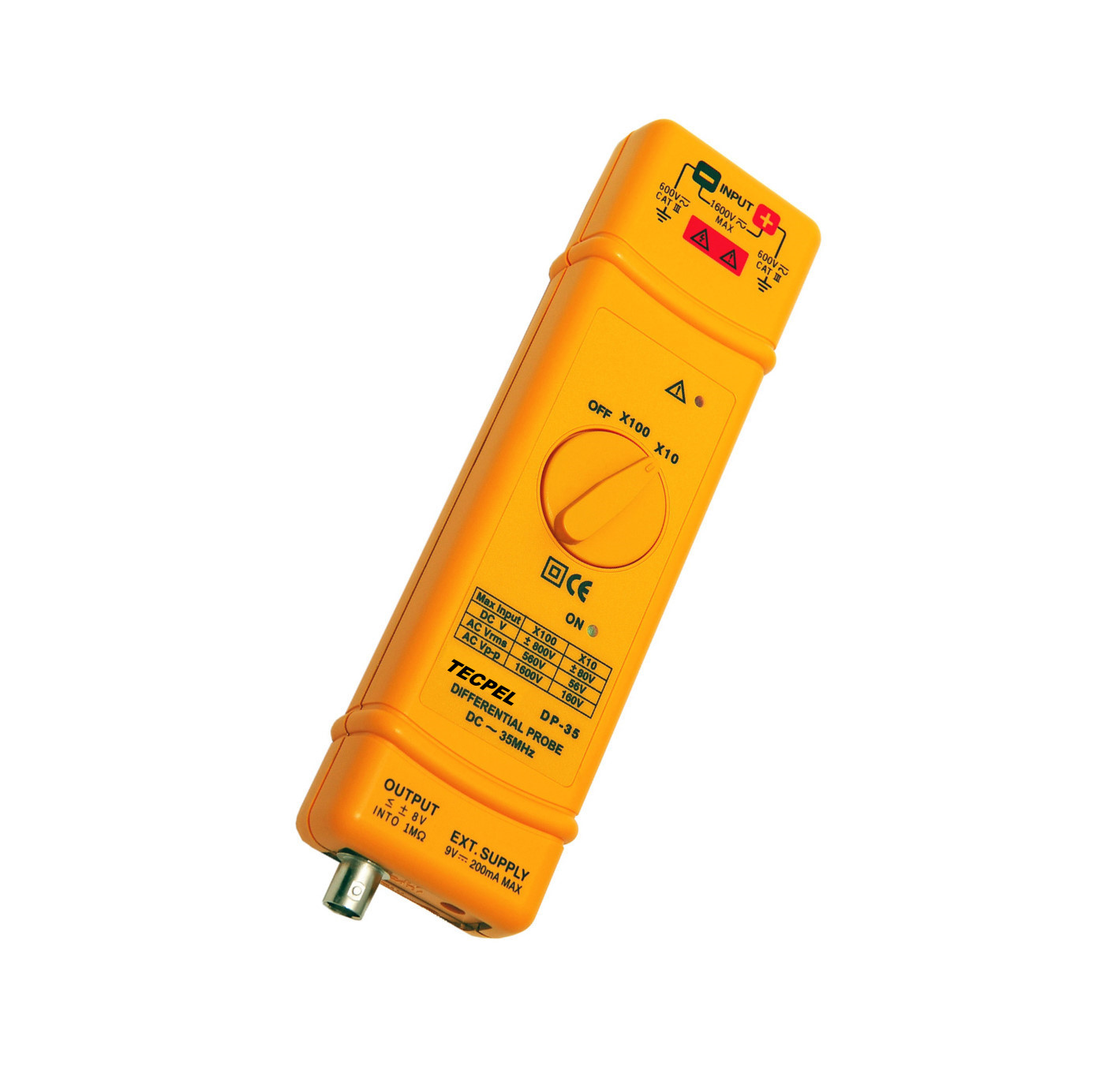
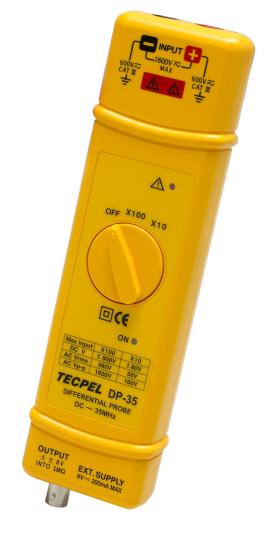
DP-35 35MHz Oscilloscope Differential Probe Product ID: DP-35
Differential Probe for Oscilloscope
DP-35 ( 35MHz /1600 Vp-p / >=10mV )
DP-35 35 MHz Differential Probes for Oscilloscopes
Separating Design(Standard No.114205) Convenient & Durable.
SPECIFICATIONS:
(1) Bandwidth:
DC - to 35 MHz (-3 dB) for x 100
DC - to 25 MHz (for attenuation x 10)
(2) Attenuation: x 10, or x 100
(3) Accuracy: +/- 2%
(4) Voltage Input Ranges (DC + AC peak to peak):
≦ 160 Vp-p for x 10, (i.e about 56 V RMS or ± 80 V DC)
≦ 1600 Vp-p for x 100, (i.e about 560 V RMS or ± 800 V DC)
(5) Permitted Max Input Voltage
Max differential voltage: 1600 V (DC + AC peak to peak)
Max voltage between each input terminal and ground: 600 V RMS
(6) Input Impedance:
Differential: 9 MΩ // 1.7 pF
Between terminals and ground: 4.5 MΩ // 3.4 pF
(7) Output: ± 8.0 V
(8) Output Impedance: 50 Ω
(9) Rise Time: 10 ns for x 100; 14 ns for x 10
(10) Rejection Rate on Common Mode:
60 Hz: >80 dB ; 100 Hz: >60 dB ; 1 MHz: >50 dB
(11) Power Supply: External 9 V DC power supply.
(12) Consumption: 200 mA about (9 V DC)
SPECIFICATIONS:
(1) Bandwidth:
DC - to 35 MHz (-3 dB) for x 100
DC - to 25 MHz (for attenuation x 10)
(2) Attenuation: x 10, or x 100
(3) Accuracy: +/- 2%
(4) Voltage Input Ranges (DC + AC peak to peak):
≦ 160 Vp-p for x 10, (i.e about 56 V RMS or ± 80 V DC)
≦ 1600 Vp-p for x 100, (i.e about 560 V RMS or ± 800 V DC)
(5) Permitted Max Input Voltage
Max differential voltage: 1600 V (DC + AC peak to peak)
Max voltage between each input terminal and ground: 600 V RMS
(6) Input Impedance:
Differential: 9 MΩ // 1.7 pF
Between terminals and ground: 4.5 MΩ // 3.4 pF
(7) Output: ± 8.0 V
(8) Output Impedance: 50 Ω
(9) Rise Time: 10 ns for x 100; 14 ns for x 10
(10) Rejection Rate on Common Mode:
60 Hz: >80 dB ; 100 Hz: >60 dB ; 1 MHz: >50 dB
(11) Power Supply:
External 9 V DC power supply.
(12) Consumption: 200 mA about (9 V DC)
- FEATURES
- FEATURES
- The DP-25 FET input differential probe provieds a safe means of measuring circuits with floating potentials up to 1000 V ( DC+ peak AC ) from ground and 1300V ( DC + peak AC ) differential.
- The DP-25 converts the high voltage differencial input signal to a low voltage ground refereced signal for display on any Oscilloscope.
- The output BNC of DP-25 is calibrted to drive a high impedance ( 1M Ohm) load.
- INSTRUCTION FOR USE
- Connect the output BNC of DP-25 to the input BNC of the Oscilloscope by the accessory BNC cable.
- Adjust the vertical offset of the Oscilloscope if necessary.
- Set the select proper range of the DP-25 and the V / DIV of the Oscilloscope according to the scale conversion chart.
- Scale conversion chart : The effective V / DIV is the attenuation factor of x 20, x 50, x 200 multiplied by the scale factor of the Oscilloscope. It will be twice when the 50 Ω load was used. For example, with the range set at x 200,
- and the scope set to 0.5 V / DIV, the effective V / DIV equals 200 x 0.5 or 100 V, with the 50 Ohm load was used, it becomes 200V, the power consumption will increase too.
- NOTE:If the voltage of the input signal exceeeds the linear range of the setting range.The signal output of
- the DP-25 would not accurately, the wave form display will be cut off.
- WARNING
- WARNING
- Do not use DP-25 above 1000v ( DC + peak AC ) between ground and the input or 1,300V ( DC + peak AC ) between the input lead.
- Do not operate DP-25 in wet or damp condition.
- Do not operate DP-25 in an explosive atmosphere.
- Do not immerse DP-25 in liquids.
- Do not operated DP-25 without covers.
- Please change the battery when the ""LOW BATT "" LED is lighted. At this time DP-25 can operate but not guaranteed the accuracy.
- DP-25 can not operate if both POWER and LOW BATT LED are not light.
- FEATURES
- The DP-25 FET input differential probe provieds a safe means of measuring circuits with floating potentials up to 1000 V ( DC+ peak AC ) from ground and 1300V ( DC + peak AC ) differential.
- The DP-25 converts the high voltage differencial input signal to a low voltage ground refereced signal for display on any Oscilloscope.
- The output BNC of DP-25 is calibrted to drive a high impedance ( 1M Ohm) load.
- INSTRUCTION FOR USE
- Connect the output BNC of DP-25 to the input BNC of the Oscilloscope by the accessory BNC cable.
- Adjust the vertical offset of the Oscilloscope if necessary.
- Set the select proper range of the DP-25 and the V / DIV of the Oscilloscope according to the scale conversion chart.
- Scale conversion chart : The effective V / DIV is the attenuation factor of x 20, x 50, x 200 multiplied by the scale factor of the Oscilloscope. It will be twice when the 50 Ω load was used. For example, with the range set at x 200,
- and the scope set to 0.5 V / DIV, the effective V / DIV equals 200 x 0.5 or 100 V, with the 50 Ohm load was used, it becomes 200V, the power consumption will increase too.
- NOTE:If the voltage of the input signal exceeeds the linear range of the setting range.The signal output of
- the DP-25 would not accurately, the wave form display will be cut off.
SPECIFICATIONS:
(1) Bandwidth:
DC - to 35 MHz (-3 dB) for x 100
DC - to 25 MHz (for attenuation x 10)
(2) Attenuation: x 10, or x 100
(3) Accuracy: +/- 2%
(4) Voltage Input Ranges (DC + AC peak to peak):
≦ 160 Vp-p for x 10, (i.e about 56 V RMS or ± 80 V DC)
≦ 1600 Vp-p for x 100, (i.e about 560 V RMS or ± 800 V DC)
(5) Permitted Max Input Voltage
Max differential voltage: 1600 V (DC + AC peak to peak)
Max voltage between each input terminal and ground: 600 V RMS
(6) Input Impedance:
Differential: 9 MΩ // 1.7 pF
Between terminals and ground: 4.5 MΩ // 3.4 pF
(7) Output: ± 8.0 V
(8) Output Impedance: 50 Ω
(9) Rise Time: 10 ns for x 100; 14 ns for x 10
(10) Rejection Rate on Common Mode:
60 Hz: >80 dB ; 100 Hz: >60 dB ; 1 MHz: >50 dB
(11) Power Supply:
External 9 V DC power supply.
(12) Consumption: 200 mA about (9 V DC)
(1) Bandwidth:
DC - to 35 MHz (-3 dB) for x 100
DC - to 25 MHz (for attenuation x 10)
(2) Attenuation: x 10, or x 100
(3) Accuracy: +/- 2%
(4) Voltage Input Ranges (DC + AC peak to peak):
≦ 160 Vp-p for x 10, (i.e about 56 V RMS or ± 80 V DC)
≦ 1600 Vp-p for x 100, (i.e about 560 V RMS or ± 800 V DC)
(5) Permitted Max Input Voltage
Max differential voltage: 1600 V (DC + AC peak to peak)
Max voltage between each input terminal and ground: 600 V RMS
(6) Input Impedance:
Differential: 9 MΩ // 1.7 pF
Between terminals and ground: 4.5 MΩ // 3.4 pF
(7) Output: ± 8.0 V
(8) Output Impedance: 50 Ω
(9) Rise Time: 10 ns for x 100; 14 ns for x 10
(10) Rejection Rate on Common Mode:
60 Hz: >80 dB ; 100 Hz: >60 dB ; 1 MHz: >50 dB
(11) Power Supply:
External 9 V DC power supply.
(12) Consumption: 200 mA about (9 V DC)